What are the JTAG signals?
What are the JTAG signals?
JTAG boundary scan technology provides access to many logic signals of a complex integrated circuit, including the device pins. The signals are represented in the boundary scan register (BSR) accessible via the TAP. This permits testing as well as controlling the states of the signals for testing and debugging.
What is JTAG interface used for?
Using a simple four-pin interface, JTAG / boundary scan allows the signals on enabled devices to be controlled and monitored without any direct physical access.
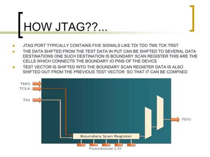
What is TMS signal in JTAG?
TMS (Test Mode Select) – this signal is sampled at the rising edge of TCK to determine the next state. TDI (Test Data In) – this signal represents the data shifted into the device’s test or programming logic. It is sampled at the rising edge of TCK when the internal state machine is in the correct state.
Is JTAG a serial interface?
Communication between your computer and the JTAG controller is usually done through a serial interface.
What is J Link Programmer?
The J-Link BASE is a USB powered JTAG debug probe supporting a large number of CPU cores. Based on a 32-bit RISC CPU, it can communicate at high speed with the supported target CPUs. J-Link is used around the world in tens of thousand places for development and production (flash programming) purposes.
What is UART and JTAG?
JTAG is a serial programming / data access protocol designed for interfacing with microcontrollers and similar devices. A UART is a chip or sub-component of a microcontroller which provides the hardware to generate an asynchronous serial stream such as RS-232 or RS-485.
What is the use of JTAG in microcontroller?
JTAG is an in-system debugging tool which allows you to manipulate and examine the status of a supported AVR while it is running in a circuit. JTAG allows the user to stop execution at any time, the manipulation of the AVR’s internal registers and much more.
What is JTAG in FPGA?
JTAG allows the user to test all the different interconnects in the FPGA connecting various integrated circuits, without having to physically probe the connections. This is a pretty major advantage when programming a board, as this can all be done by software.
What is J-Link JTAG?
The J-LINK is a JTAG emulator designed for ARM cores. It connects via USB to a PC running Microsoft Windows 2000 or later. The J-LINK ULTRA+, J-LINK PRO and J-LINK EDU JTAG emulators are compatible to the J-Link and use the same software. The J-TRACE includes a trace function.
What is J-Link segger?
SEGGER Microcontroller J-Link In-Circuit Debuggers are USB-powered JTAG emulators based on a 32-bit RISC CPU. These Debuggers can communicate at high speed with a large number of supported target CPU cores. The J-Link debuggers support multiple target interfaces that include JTAG, SWD, FINE, SPD, and ICSP.
What is difference between UART and RS232?
RS232 is a signalling protocol that defines things like pin assignments, voltage levels and so forth. UART is a hardware transceiver that implements some signalling protocol. A UART can implement RS232, but it can also implement other serial protocols, such as RS485, TTL which define different voltage levels etc.
How does JTAG chain work?
If a circuit contains more than one JTAG-compliant device, these can be linked together to form a JTAG chain. In a JTAG chain the data output from the first device becomes the data input to the second device; the control and clock signals are common to all devices in the chain.
What does JTAG stand for?
JTAG stands for Joint Test Action Group, which is an IEEE work group defining an electrical interface for integrated circuit testing and programming. → port.JTAG (this article) → port.JTAG.cables (homemade cables) → port.JTAG.cable.buffered or buffered + redirect from something.wiggler to this article.
What is the purpose of a JTAG connector in computing?
JTAG is a common hardware interface that provides your computer with a way to communicate directly with the chips on a board. It was originally developed by a consortium, the Joint (European) Test Access Group, in the mid-80s to address the increasing difficulty of testing printed circuit boards (PCBs).
How does JTAG work?
First,the instruction mode is selected.
What is a JTAG for?
JTAG (named after the Joint Test Action Group which codified it) is an industry standard for verifying designs and testing printed circuit boards after manufacture. JTAG implements standards for on-chip instrumentation in electronic design automation (EDA) as a complementary tool to digital simulation.
